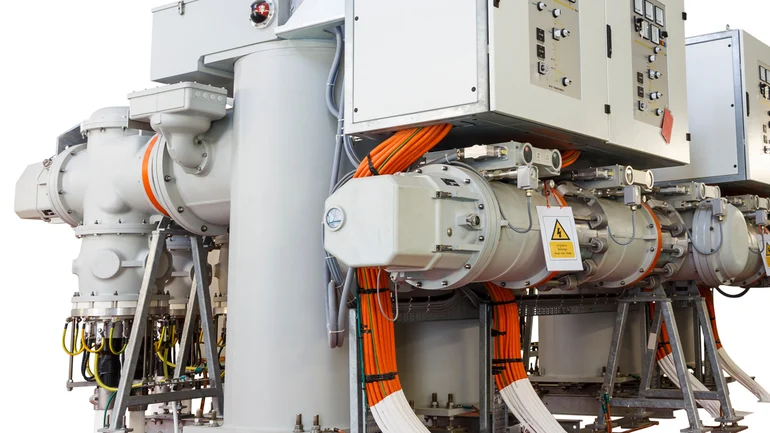
Gas insulated switchgear (GIS) are installed in some 132kV substations to control, protect and isolate power systems.
There may be times where the cable termination connections are not completely secured to the switchgear. Due to cooling, during large and relatively fast load reductions, potentially two scenarios could happen.
1. The cable conductor can contract along its length, leading it and the insulation to pull out from the rest of the termination, potentially resulting in partial discharge (PD) causing damage to the termination
2. The cable conductor contracts along its length leaving the insulation intact, potentially leading to partial discharge activity resulting in the termination insulation becoming compromised and causing damage to the cable sealing end (CSE).
Currently there isn’t a non-intrusive way of testing these terminations in situ to determine if they’re mechanically secured. An intrusive inspection to examine the terminations could result in permanent damage to the equipment, therefore making it necessary to fit new lengths of cable to the termination.
The expense of an intrusive inspection would be disproportionate to the perceived risk and lengthy power outages.
The Solution
The project is currently developing a monitoring system capable of detecting faults in the cable sealing ends (CSE) before they cause a power network system failure (known as a flashover), resulting in customer outage.
The solution will record and analyse readings from the CSE and provide early warnings of potential faults, enabling the network to respond and resolve any detected issues accordingly.
Approach
The EIC launched a call for innovation on behalf of SP Transmission, as part of which Elimpus’ idea was shortlisted. All parties were then subsequently supported with the development of project plan and assisted the completion of legal contractual arrangements in accordance with the Network Innovation Allowance (NIA) framework.
The Project
The project started in July 2023 and has eight stages. The aim is to develop a hardware capable of measuring temperature, partial discharge and vibration simultaneously within the system. This hardware will continuously monitor these critical variables non-invasively and provide fault alarms, ensuring any issues are promptly detected and resolved.
Key Lessons:
1. The thermal modelling of the CSE required 3D modelling as opposed to 2D for a more reliable analysis of components
2. Reliance on third parties for relevant project information has caused delays due to queries around intellectual property.
New Steps
Following the thermal modelling of analysis of the CSE, the next step is to design and manufacture a suitable monitoring device for installation in a substation to monitor/analyse the CSE data.